
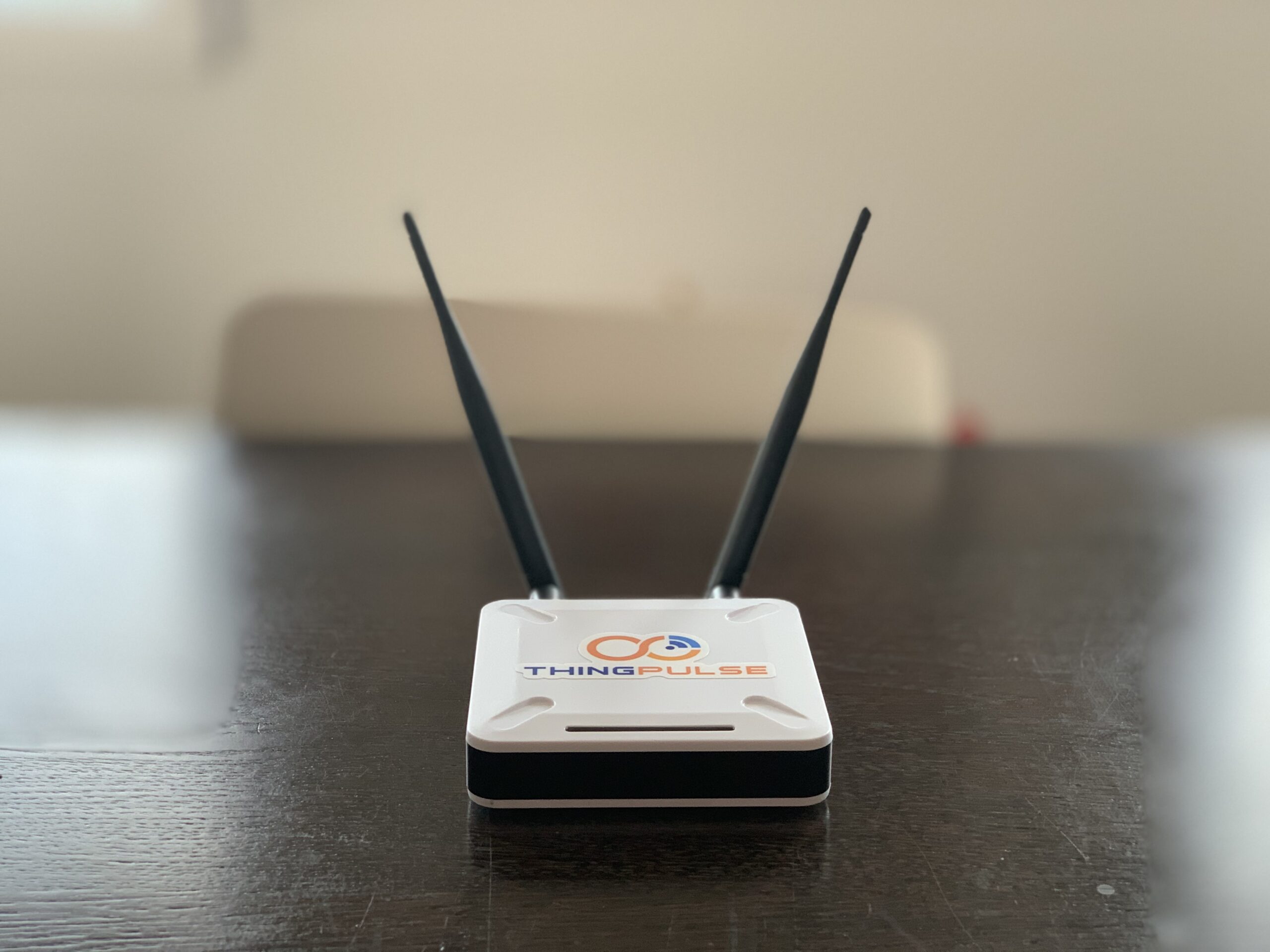
Did you ever get to the point where one ESP module just wasn’t enough? In this article, we are going to present the ThingPulse ESPGateway and why we designed it this way.
At ThingPulse we mostly build products which we want ourselves and which we can’t find in the market. Once you have the skills to design new hardware it’s relatively easy to try out an idea and see if there is resonance in the (maker) community. The ESPGateway is such a device. With several projects around the ESP32 I got to the point where I got to the limits of just one ESP and worked around it by adding a second ePulse module on the bread board. This is easy enough, but bread board designs are not very stable and often live very long in my house.
So wouldn’t it be nice to have a device in an attractive enclosure which I could use to try out those ideas and also keep them running for a longer time without the complaints of other members of the family in my house?
Design Decision 1: Two ESP32 Modules
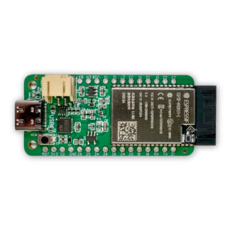
The first design decision was relatively easy: I needed two ESP32 modules. The two modules would be connected to each other by using two wires to save GPIO pins for other applications. The software would probably use the Serial protocol for communication, since it is easy to implement two way communication between two ESP32.
In many of our past projects we decided for the ESP32-WROVER modules. They are compact, have a metal shield and were certified for certain telecommunication agencies. And they come with ample memory (4MB flash and 8MB PSRAM).
Design Decision 2: External Antennas
External antennas can increase the range of WiFi and Bluetooth a lot, compared to the onboard PCB antenna of the regular modules. Using external antennas with the ESP32-WROVER modules is easy. The modules come in various flavors: the ESP32-WROVER-IB comes with an IPEX connector, while the ESP32-WROVER-B (without the “I”) is wired to use the PCB antenna.
All you need then is a cable with an IPEX connector on one end and an SMA connector on the other.
Design Decision 3: Only one UART Chip
When you have two ESP32 modules you need to be able to programming both of them. You could have two USB plugs and two Serial-To-USB chips including the circuitry to put the ESP32 into programming mode. But that presents you to new problems: what if they user tries to program both at the same time? Then you might possibly have to different potentials of power from the two USB interfaces which could lead to all kind of nasty problems.
So why not just use on USB (Type-C) plug and also only one USB-to-Serial chip? Then let the user decide to which ESP32 the UART chip is connected by selecting it with a switch. This switch is placed on the back of the device and while it might be confused with a power switch it lets you selected the serial path from PC – USB – UART – ESP32. This turned out to work really well and is also very convenient. After programming you can easily switch serial monitoring from one ESP32 to the other. Having two UARTs would also be hard to manage on the computer side: what is the serial port name of ESP32-1 and what is the name of ESP32-2?
Design Decision 4: Blinky – Blinky ( – Blinky – Blinky)
The enclosure we use for the ESPGateway as a slot for displaying status LEDs. So why not add some WS2812b-mini RGB LEDs to the mix? Each of the two ESP32 modules can control and address two RGB LEDs. You can decide in your program code what you want to display: WiFi activity, BLE activity, the current state of the boot process? You can also decide to use the RGB for a Knight-Rider-like light bar. That’s all up to you!
Design Decision 5: Maker Friendly Design
A while ago we started to lead out as many GPIO pins as possible to 2.54mm pads. We want you to be able to add your own sensor, displays, actuators. And this should be as easy as possible. And with the power of two ESP32 modules the number of available GPIO pins is really high! For each of the two ESP32 modules we led out 18 GPIO pins, 3V3 and GND. 36 GPIO pins in total!
Design Decision 6: Prepare For LoRaWAN
Here at ThingPulse we love LoRaWAN. So we wanted to give the option to easily extend our communication gateway with even one more communication module: The board is prepared to take one RN2483 LoRaWAN module. The antenna pins can be accessed through two IPEX connectors. The RN2483 is connected to only one of the two ESP32 modules which breaks the symmetry a bit. But with all this communication power we think this is probably OK;-)
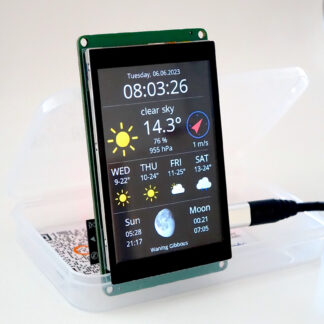
Continue Reading – Part 2
In part two of this blog post we will discuss possible applications of the ESPGateway.
Already hooked?
Is it possible to make a Helium (LoRaWAN) hotspot miner?
In theory: maybe. But since last year helium miners must be certified by Helium and the software running on them require keys/certificates from Helium to run. Only certified manufacturers can get those.
do you supply any software example programs with the device? For example, as you display in one of the pictures, “Several ESP’s transmitting Temp and Hum readings. Example in your ESP gateway how to read in those individual ESP’s, condense the data into serial communications to the second on-board ESP, then transmit that via MQTT to RPI. Also any example code and HW requirement on the rpi/Code-Red side. I have purchase a couple of your projects/products in the past nd wouldn’t have been able to get it all working without some of the sample code that come with them.
Thanks for asking William. We do have sample applications. They are listed on the product page at https://thingpulse.com/product/espgateway/. Furthermore, just the other day Dani posted an article on his personal blog at https://blog.squix.org/2023/04/esp32-cheap-sensor-network-with-openmqttgateway.html about how to use the open-source OpenMQTTGateway firmware on our device.