
In this post I’m going to show you how you can monitor the power consumption of your battery driven (ESP8266/ ESP32) device. Measuring the power consumption over a full activity/ sleep cycle is the precondition to optimize your code for a longer battery runtime. Only with a reliable tool you can decide which code changes lead to less consumption. In a later post we’ll look at some tweaks we can apply to the code to get a few more days out of the battery.
As a long time professional Java developer I’m used to write applications that run on servers with lots of resources: RAM, disk space and energy consumption are rarely a limiting factor for the software we write. Developing software for embedded devices is a totally different story: memory both for flash and heap is very limited. And if you want to run your device from battery every second you are staying online counts towards the total energy bill of your battery. In our big server applications we usually say that you should first write reliable and readable code.
If your application is not fast enough or consumes too much memory you start tuning the hot spots of your code until you get the desired results. Of course, it’s really hard to turn a bad decision in your architecture into a fast performing application. I would say that these rules are also true for embedded devices: first write reliable and readable code, then start tuning. And avoid costly dead ends which are later hard to fix.
In my opinion you can’t tune a system if you don’t have reliable measurements before and after you change any factor. So how do you collect this information in an embedded device? That of course depends on what aspect you would like to improve: memory, battery runtime, connection speed, etc. In this post I’m interested in prolonging the battery life of the ESPaper.
Measuring the energy consumption of a device that consumes a few uA when it sleeps and a few hundred mA when it is awake is a special challenge: your regular multimeter might have a hard time measuring these two ranges. And we want to measure the summed up consumption over one sleep/wake cycle, not just the current drawn by the device at this very moment. You can do such a measurement with expensive tools like oscilloscopes. But if absolute consumption is not so important and you are rather interested in whether your changes have a positive or negative impact then the following setup will be the right tool for you.
The Power Monitor Hardware
To monitor the power consumption of the ESPaper I decided to use mostly the components from our Classic Starter Kit: 1x NodeMCU V1.0, 1x 0.96″ OLED display and some female-female jumpers. In addition you will need a INA219 breakout board which you can buy from Banggood. When you have all required component start wiring everything up as in depicted in the diagram below. Make sure that you connect the LiPo and Vin+ to the LiPo connector of the ESPaper.

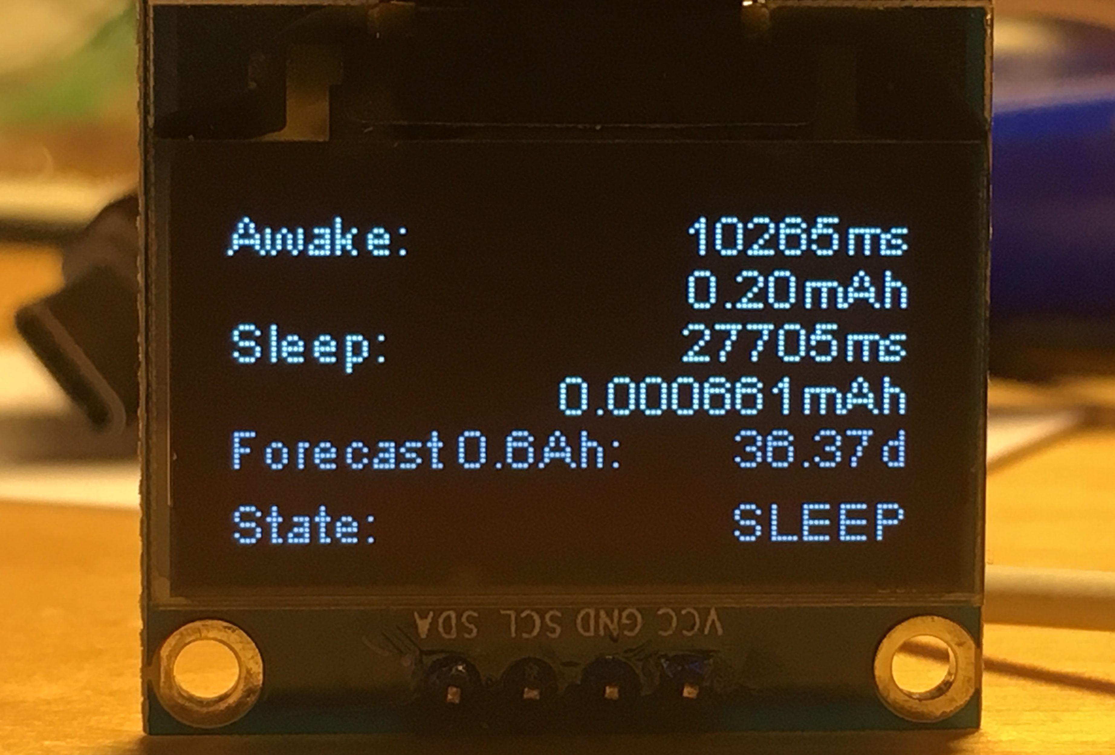
As you can see the INA219 breakout board is inserted between the LiPo battery and the ESPaper to measure the current flowing from the battery to the module. The ESP8266 then reads the measured voltage drop over the 100 0.1 Ohm burden and calculates the current from that. While this setup works well for bigger current (50-250mA) the resolution of 0.1mA gets a bit noise when the ESPaper module is sleeping. It turned out that the time the module is awake consumes so much more energy than when it is asleep we can live with that issue. The NodeMCU then displays the measured values on the 0.96″ OLED display which is very convenient to quickly read the values.
The Power Monitor Software
First a bit of theory. The whole point of the power monitor is to see how changes in the ESPaper code affect the time the device can run from one charge. The ESPaper Plus Kit comes with a 600mAh 3.7V LiPo battery. So if our device would constantly draw 20mA the device would last 30 hours (600mAh / 20mA = 30h). Now our device doesn’t constantly draw 20mA. When it is awake it draws around between 70-250mA and when it is asleep less than 100uA. That makes the calculation a bit more complicated.
We would get slightly more appropriate results if we would measure how long the device is awake and how much current it draws during that time and do the same while it is asleep. But with the power monitor we can do even better! We can sample the current every few ms and multiply that value with the time that has passed since the last sample. Then we sum up all these values and get the total consumed energy. Let’s have a look at the following diagram:

The red line is a ideal current curve of the power drawn by the device. The red boxes are the sampled area below the curve. As you can see the sample time determines how accurate this area is calculated: the shorter the sample time the more accurate the calculated consumption. Of course the red line wouldn’t be so smooth in reality. The ESP8266 usually draws a peak current of about 250mA after it wakes up and then more or less constantly draws around 70mA before it goes back to sleep.
If we want to know how long our code lasts from one battery charge we have to look at one cycle of activity and sleep and then assume that all the following cycles will behave equally. In the beginning my code required a complete cycle (~20min 10sec) to show a reliable measurement. Then I realized that we can already make a good forecast after one awake phase: the sleep phase itself is very boring: the device sleeps for 20 minutes and draws a constant amount of a few micro ampere.
Compared to the huge amount the device consumes during the awake phase the sleep phase almost only matters in its duration. The shorter the sleep phase is the more awake is the device and over the course of a long time this is what really drains your battery. One parameter in the code is the expected sleep time. If you change this in the ESPaper you also have to change it the power monitor. This little trick allows us to get a reliable guesstimate how long the device can run from a battery with a given capacity already after a few seconds.
Since we know how long the device will sleep we can extrapolate the power consumption for the total sleep phase. To track the awake phase and the sleep phase separately I used a state machine:

When the monitoring device wakes up it is in the NA state; we can’t make any forecast about consumption. When the ESPaper wakes up for the first time we switch to the AWAKE state. We can detect this by defining a threshold current (e.g 1mA). If the measured current is above this threshold the monitored device is awake. In any other case the device is sleeping. We then sum up the totally consumed energy in the awake state. After the monitored device goes back to sleep we sum up the consumed current when the device is sleeping. We then extrapolate how much energy will be consumed during the following 20 minutes until the device wakes up the next time. This means that we only have to wait about 20-30 seconds to have a stable estimation of how long the device will run!
To run the monitoring software on your ESP8266 please:
- Checkout the repository from https://github.com/ThingPulse/ESP8266PowerMonitor
- Get the ESP8266 OLED SSD1306 library from the Arduino IDE library manager or from here https://github.com/ThingPulse/esp8266-oled-ssd1306
Summary and Outlook
In this post we had a look how you can use a regular ESP8266, OLED display and INA219 breakout board to monitor the long term power consumption of an embedded device. By splitting the duty cycle of the monitored device into the “interesting” awake phase and the rather boring sleep state we can accomplish a good estimate of how long the device will run from one battery by measuring just a short time.
In the post 5 Hacks to Prolong your ESPaper’s Battery Run-Time we will have a look how we can change to code to get a few more days out the battery. Since we have to keep the awake time as short as possible we’ll try get connected to the WiFi faster by cheating a bit. If you don’t want to miss this post please follow us on Twitter @ThingPulse or by subscribing to our newsletter.
100 Ohm??? Can’t be. It’s one of those boards with marking R100 on the resistor? I’m not an expert on SMD marking, but I think it means 0.100 Ohm.
“The ESP8266 then reads the measured voltage drop over the 100 Ohm burden”
Well I think it is a 100 mOhm resistor.
Because the voltage drop in a 100 Ohm resistor will be to high (at 100mA in a 100 Ohm resistor the voltage drop is 10V)
@FailureAnalysis and @fdufnews: you are absolutely right, it’s 0.1 Ohm. Thank you for paying attention!
Hi, this looks really cool and useful.
One question, I’ve built devices that run in 3 states (on a board with both an atmega328p and an ESP8266). I’d like to measure 3 states, being..
1. Everything asleep (in the very low uA from my measurements)
2. atmega awake (in the tens of uA range)
3. both the atmega and the esp8266 awake (in the tens to hundreds of mA range).
Is it just a matter of modifying the statemachine above to cater for this scenario ?
Hi lakid
Yes, this should not be a problem. I’m using the consumption itself to detect the states, so if you can define the thresholds you should be good to go. Also, if you don’t mind running a whole duty cycle to measure the consumption you don’t even need the state machine. The state machine just helps to measure the awake state and estimate/forecast the consumption for the whole duty cycle. And in addition, you could also fine tune the monitor by connecting it to the monitored system over UART/serial connection or some dedicated pins. The monitored system could then set some pins to HIGH or output specific messages depending on the internal state and the monitor could read this to be even more precise in the detected state. Less guessing, more knowing…
Hi there,
I optimized the code, and in my case it runs on an Arduino Nano now, since it is not required to run on an ESP8266.
The forecast is calculated after one complete cycle (Awake + Sleep) now, as this considers the total cycle time into the calculation dynamically, which gives more accuracy. Also I rewrote the state machine using a more elegant switch/case construction.
In the original hardware design, I don’t understand why there are two separate I2C-busses used. This is not required.